Models
SVB: Brass
- Specially designed for flammable fluids
- UL 842 Approved
- API 614 & 520 Approved
- Chatter-free operation
- Mount in any position
- Suitable for continuous duty
Size Range: 3/8″ – 2″
Pressures: 3 – 500 psi
Flow Rate: Up to 150 gpm
SVB: Brass
Size Range: 3/8″ – 2″
Pressures: 3 – 500 psi
Flow Rate: Up to 150 gpm
Fulflo valves can be mounted in any position. A tee may be inserted in the pump discharge line to mount the valve. The correct size of the valve should be installed, preferably matching the pump discharge line. Screw the valve into the nipple in the tee. When the valve is used for frequent bypassing of oil under pressure, its outlet should be piped back to the tank. Care must be taken to have the discharge well below the oil level in the tank to prevent air entrainment and erratic operations.
Only if the valve is used as safety or overload relief and operates infrequently may its discharge be piped back into the pump suction line. Frequent or continuous operation under these conditions will cause excessive heating of the oil and possible damage.
Valve may be set with a hand pump for cracking pressure. It will be noted that the maximum set pressure is limited by the collar “J” soldered to the adjusting screw “C”.
If a test stand is available, valve should be connected to the discharge header with the pump bypass open, and the bypass gradually closed until the desired pressure registers on the gauge. Adjust valve adjusting screw until valve slightly bleeds at the set bypass pressure and lock adjusting screw.
If valve is required to bypass a given amount of fluid at a given pressure, a test stand having a flow meter in the pump discharge line must be available. With valve adjusted for cracking pressure as above, continue closing bypass until the required flow registers on the flow meter and observe pressure. Re-adjust pressure, if necessary, to obtain desired pressure at desired flow.
Fulflo valves provided reliable “chatter-free” operation when the system is free of abrasives and foreign matter. Continuous filtration of the liquid used is strongly recommended.
To dismantle valve for inspection and cleaning:
Inspect valve bore and piston for wear or scoring. Replace broken or damaged parts. Clean all parts thoroughly and re-assemble by reversing the above procedure.
| Symbol Number | Designation | Code | Description |
|---|---|---|---|
| 1 | Style | S | Underwriter Listed |
| 2 | Series | V | – |
| 3 | Material | B | Brass |
| 4 or 5 | Size | -25 -35 -45 -55 -65 -75 -85 |
3/8” 1/2” 3/4” 1” 11/4” 11/2” 2 |
| 6 | Spring | /AS /US /WS /XS /YS /ZS |
Pressure Range = 3 – 10 psi (spring color: black) Pressure Range = 7 – 35 psi (spring color: red) Pressure Range = 30 – 100 psi (spring color: green) Pressure Range = 60 – 175 psi (spring color: yellow) Pressure Range = 150 – 350 psi (spring color: white) Pressure Range = 300 – 500 psi (spring color: blue) |
| 7 | Piston | 0 1 2 3 |
Hardened Steel, deep groove Stainless Steel, deep groove Hardened Steel, shallow groove Stainless Steel, shallow groove |
| S | V | B | -55 | ZS | 0 | |||||||
| Underwriter Listed | Series | Brass | 1” | Spring | Hardened Steel Piston, Deep Groove | |||||||
NOTE: A definite pressure setting is required due to Underwriter restrictions. A limiting device is furnished to prevent over-adjustment more than 25% above set pressure.
Specify:
1. Valve Model Number
2. Spring Letter
3. Piston Number
4. Pressure Setting
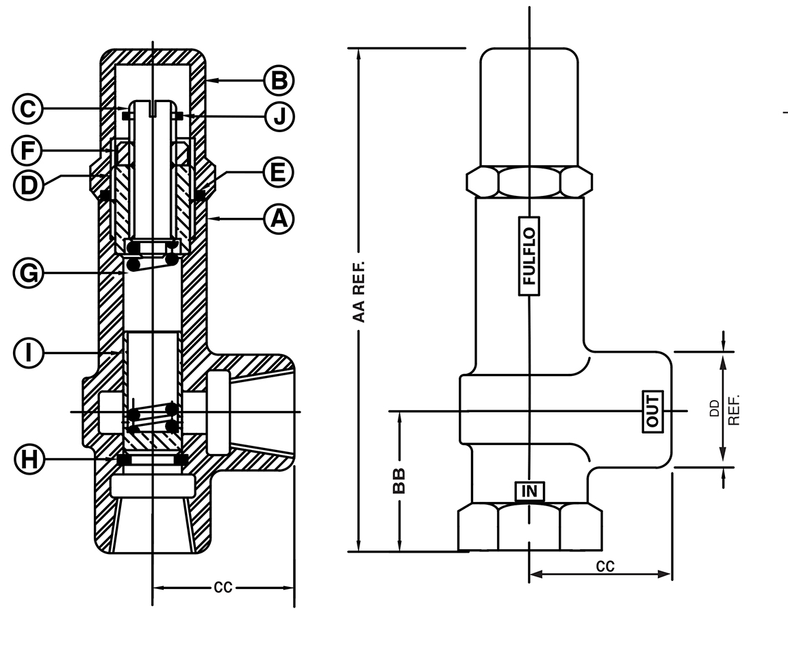
| Pipe Size | “U.L.” Symbol | AA | BB | CC | DD REF |
| 3/8’” | SVB-25 | 511/32 | 13/8 | 13/8 | 13/8 |
| 1/2” | SVB-35 | 63/16 | 111/16 | 17/16 | 17/16 |
| 3/4” | SVB-45 | 615/16 | 115/16 | 113/16 | 111/16 |
| 1” | SVB-55 | 87/32 | 29/32 | 29/32 | 21/16 |
| 11/4“ | SVB-65 | 99/16 | 29/16 | 29/16 | 21/2 |
| 11/2“ | SVB-75 | 111/16 | 211/16 | 211/16 | 27/8 |
| 2″ | SVB-85 | 13 | 3 | 3 | 31/4 |
Valve Size |
|||||||||||||
| Sym. | Name | 3/8” | 1/2” | 3/4” | 1” | 11/4” | 11/2” | 2” | |||||
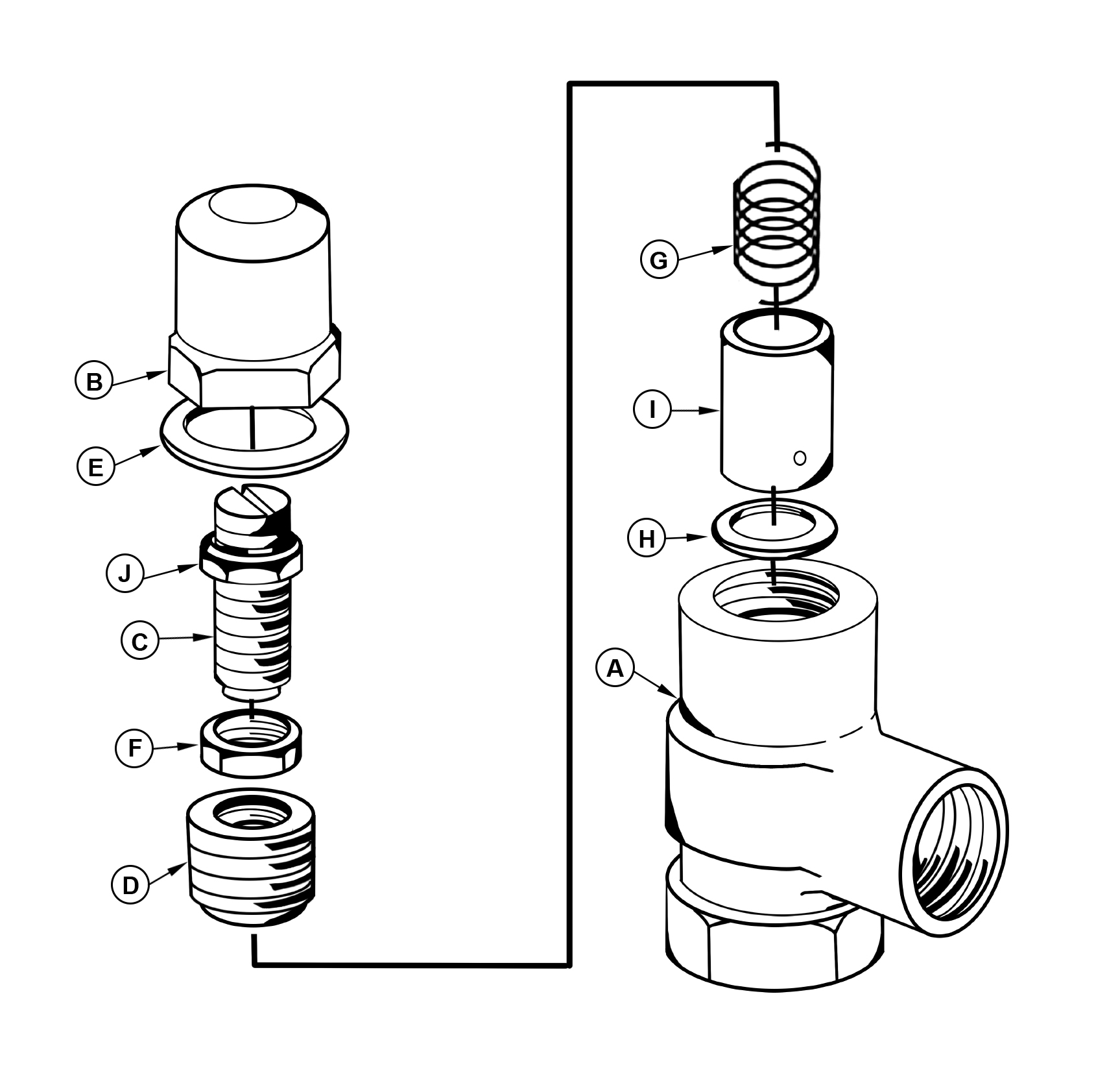
| A | Body | 200-B | 300-B | 400-B | 500-B | 600-B | 700-B | 800-B | |||||
| B | Cap | 201-B | 301-B | 401-B | 501-B | 601-B | 701-B | 801-B | |||||
| C | Adjusting Screw | 202-B | 302-B | 402-B | 502-B | 602-B | 702-B | 802-B | |||||
| D | Retainer | 203-B | 303-B | 403-B | 503-B | 603-B | 703-B | 803-B | |||||
| E | Gasket | 204 | 304 | 404 | 504 | 604 | 704 | 804 | |||||
| F | Lock Nut | 205-S | 305-S | 405-S | 505-S | 605-S | 705-S | 805-S | |||||
| G | Spring | See Chart* | See Chart* | See Chart* | See Chart* | See Chart* | See Chart* | See Chart* | |||||
| H | Stop Ring | 208-B | 308-B | 408-B | 508-B | 608-B | 708-B | 808-B | |||||
| I | Piston Hardened Steel, deep groove Stainless Steel, deep groove Hardened Steel, shallow groove Stainless Steel, shallow groove |
– 206-G 206-AG 206 206-A |
– 306-G 306-AG 306 306-A |
– 406-G 406-AG 406 406-A |
– 506-G 506-AG 506 506-A |
– 606-G 606-AG 606 606-A |
– 706-G 706-AG 706 706-A |
– 806-G 806-AG 806 806-A |
|||||
| J | Limit Column | 221-B | 321-B | 421-B | 521-B | 621-B | 721-B | 821-B | |||||
All valve tests 110˚F. to 120˚F. Oil Viscosity 150 SSU at 100˚F
(Charts good from 30 to 500 SSU)
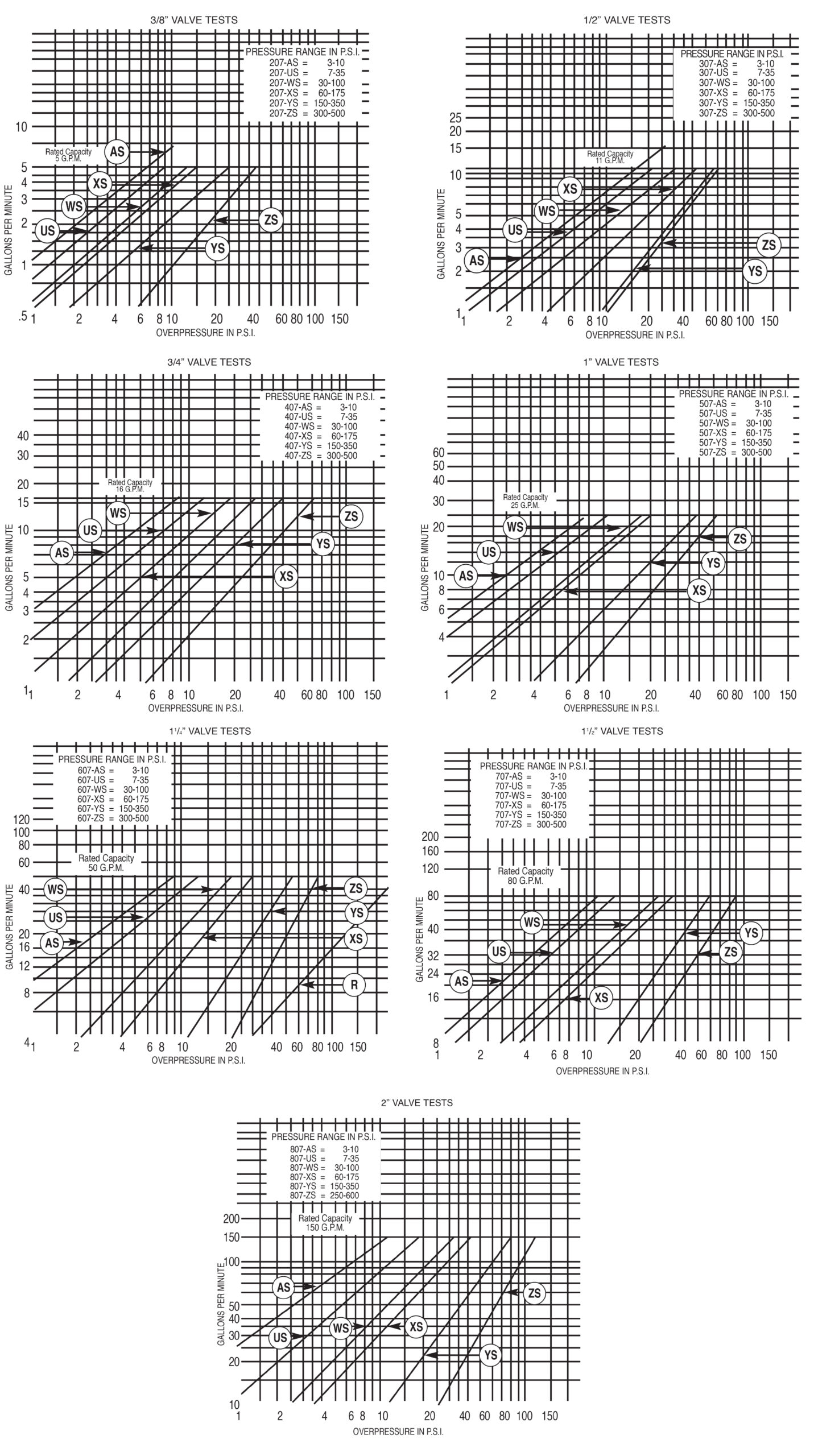
Overpressure: The pressure increase or accumulation above the set pressure when the valve is discharging flow.
