Models
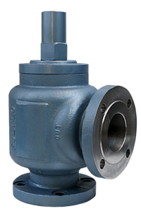
AAPF: Cast Iron
ACPF: Cast Steel
ASSPF: Stainless Steel
- API 520 & 614 Approved
- Chatter-free operation
- Mount in any position
- Suitable for continuous duty
Size Range: 2.5″, 3″ & 4″
Pressures: 50 – 500 psi
Flow Rate: 150 – 600 gpm
AAPF: Cast Iron
ACPF: Cast Steel
ASSPF: Stainless Steel
Size Range: 2.5″, 3″ & 4″
Pressures: 50 – 500 psi
Flow Rate: 150 – 600 gpm
Fulflo valves can be mounted in any position. A tee may be inserted in the pump discharge line to mount the valve. The pipe lines carrying the heavy valves must be well supported and overhung weights avoided. The correct size of valve must be used, preferably equal to the size of the pipe line to which they are connected. Flanged valves (AADF and ACDF) are bolted to the companion flange which may be threaded or welded to the pipe. The outlet of the valve should be piped to the supply tank, unless specific applications call for alternate piping of return lines. Care must be taken to have the discharge well below the oil level in the tank to prevent air entrainment and erratic operation.
Valve may be set with a hydraulic hand pump for cracking pressure. If a test stand is available, valve should be connected to the discharge header with the pump bypass open, and the bypass gradually closed until the desired pressure registers on the gauge. For Internal Pilot Operated valves, adjust valve adjusting screw until approximately 5-7 GPM is flowing through the valve, at that point the main piston will open and then the valve will be considered at the set point, then lock adjusting screw. If a valve is required to bypass a given amount of fluid at a given pressure, a test stand having a flow meter in the pump discharge line must be available. With a valve adjusting for cracking pressure as above, continue closing bypass until the required flow registers on the flow meter and observe pressure. Readjust pressure, if necessary, to obtain desired pressure at desired flow.
Fulflo valves provide reliable “chatter-free” operation when the system is free of abrasives and foreign matter. Continuous filtration of the liquid used is strongly recommended.

To dismantle the valve for inspection or cleaning:
*CAUTION: Hold in vise–balance spring “O” is under heavy compression
Inspect bores of both piston retainer “K” and cylinder “M”. Inspect pistons “N” and “P” for wear or scoring. Replace broken or damaged parts. Clean all parts thoroughly and re-assemble as follows:
| Symbol Number | Designation | Code | Description |
|---|---|---|---|
| 1 | Series | A | |
| 2 | Material | A C SS |
Cast Iron Cast Steel Stainless Steel |
| 3 | Type | D P |
Direct Acting Internal Pilot Operated |
| 4 & 5 | Size | 09 10 11 |
21/2” 3” 4” |
| 6 | Connection | None F |
Screw Type (21/2″ and 3” only) Flange |
| 7, 8, 9 | ASA Flange Rating |
150# 300# 600# |
|
| 10 | Flange Style Only |
A B C D |
Raised Face, Staggered Bolt Centers Smooth Face, Staggered Bolt Centers Raised Face, Bolts on Valve Centerline Smooth Face, Bolts on Valve Centerline |
| 11 | O-Ring Material |
R RV RS RT RA EPR RN |
Buna O-Ring Cap Seal (Standard) Viton O-Ring Cap Seal Silicone O-Ring Cap Seal Teflon O-Ring Cap Seal Aflas O-Ring Cap Seal Ethylene Propylene Neoprene |
| 12 | Piston Material |
/HS /SS /3SS |
Hardened Steel 416 Stainless Steel 303 Stainless Steel (For Stainless valves only) |
| 13 | Spring
(+/-1-5 PSI ON ALL
|
A0980D & A1190D A1080D & A1190D A1181D & A1190D |
Pressure Range = 50 – 500 psi Pressure Range = 50 – 500 psi Pressure Range = 50 – 500 psi |
| 14 | Setting | Desired Set Pressure |
ACP09F300AR |
|||||||
Specify:
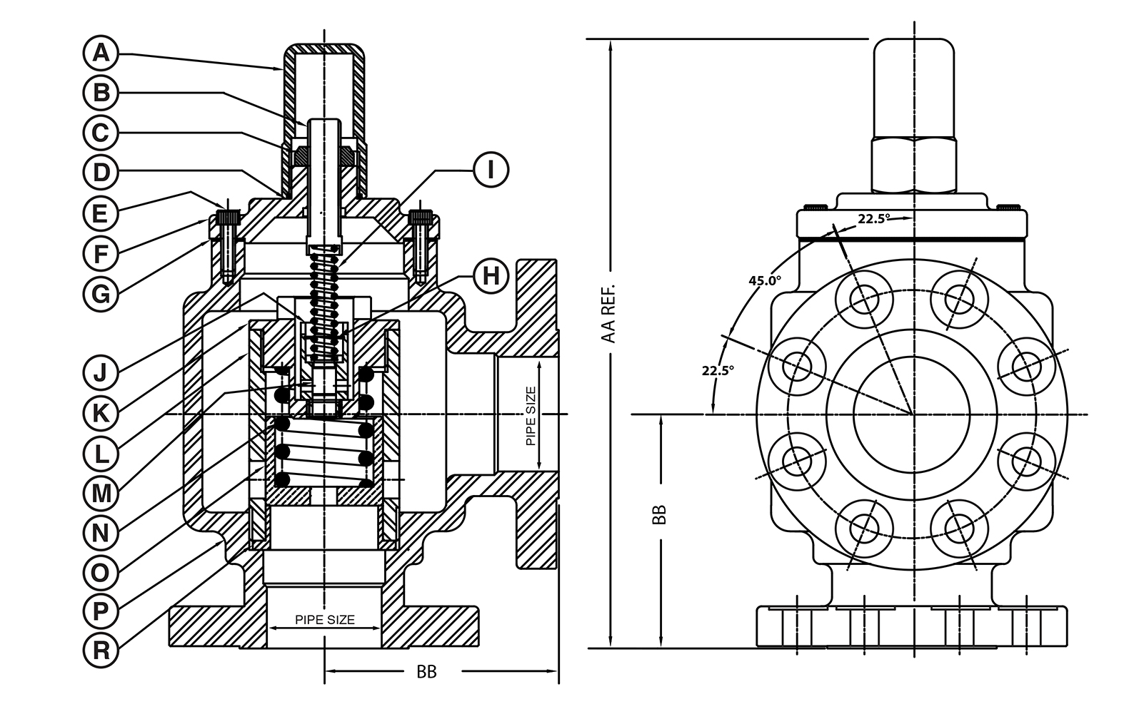
| Valve Size | Flange Rating | AA | BB |
| 21/2″ | 150# & 300# | 157/8 | 53/4 |
| 21/2″ | 600# | 161/4 | 61/8 |
| 3″ | 150# & 300# | 161/8 | 61/4 |
| 3″ | 600# | 161/2 | 65/8 |
| 4″ | 150# & 300# | 183/16 | 715/16 |
| 4″ | 600# | 183/8 | 81/8 |
Note: Refer to Engineering Section for Flange & Drilling Dimensions
Valve Size |
||||||||||||||
| Symbol | Name | Model | 21/2” | 3” | 4” | |||||||||
| A | Cap | AAP, ACP ASSP |
A1101CR A1101SSR |
A1101CR A1101SSR |
A1101CR A1101SSR |
|||||||||
| B | Adjusting Screw | AAP, ACP ASSP |
A1102C A1102SS |
A1102C A1102SS |
A1102C A1102SS |
|||||||||
| C | Lock Nut | AAP, ACP ASSP |
505-S 505-SS |
505-S 505-SS |
505-S 505-SS |
|||||||||
| D | O-Ring+ | All Models | 604-* | 604-* | 604-* | |||||||||
| E | Cap Screw | All Models | 3/8×1 SHCS | 3/8×1 SHCS | 3/8×1 SHCS | |||||||||
| F | Bonnet Cast Iron Steel Stainless Steel |
– AAP ACP ASSP |
– A0919A A0919C A0919SS |
– A1019A A1019C A1019SS |
– A1119A A1119C A1119SS |
|||||||||
| G | Gasket+ | AAP, ACP ASSP |
A0903E A0903RT |
A1003E A1003RT |
A1103E A1103RT |
|||||||||
| H | Retainer Ring+ | All Models | A1120D | A1120D | A1120D | |||||||||
| I | Pilot Spring+ | All Models | A1190D | A1190D | A1190D | |||||||||
| J | Piston Retainer+ | AAP, ACP ASSP |
A1118C A1118SS |
A1118C A1118SS |
A1118C A1118SS |
|||||||||
| K | Cylinder Retainer | AAP, ACP ASSP |
A0912C A0912SS |
A1012C A1012SS |
A1112C A1112SS |
|||||||||
| L | Cylinder+ | AAP, ACP ASSP |
A0928C A0928SS |
A1028C A1028SS |
A1128C A1128SS |
|||||||||
| M | Piston+ Hardened Steel 416 Stainless Steel 303 Stainless Steel |
0 AAP, ACP AAP, ACP ASSP (only) |
0 A1115C A1115D A1115SS |
0 A1115C A1115D A1115SS |
0 A1115C A1115D A1115SS |
|||||||||
| N | Balance Spring+ | All Models | A0980D | A1080D | A1181D | |||||||||
| O | Piston+ Hardened Steel 416 Stainless Steel 303 Stainless Steel |
– AAP, ACP AAP, ACP ASSP (Only) |
0 A0936C A0936D A0936SS |
0 A1036C A1036D A1036SS |
0 A1136C A1136D A1136SS |
|||||||||
| P | Body | AAP ACP ASSP |
A0900F A0900CF A0900SSF |
A1000AF A1000CF A1000SSF |
A1100AF A1100CF A1100SSF |
|||||||||
| R | Retaining Bushing | AAP, ACP ASSP |
A0911C A0911SS |
A1011C A1011SS |
A1111C A1111SS |
|||||||||
+ Recommended spare parts
* See Assembly Number Identification Chart, Symbol Number 13
All valve tests 110˚F. to 120˚F. Oil Viscosity 150 SSU at 100˚F
(Charts good from 30 to 500 SSU)
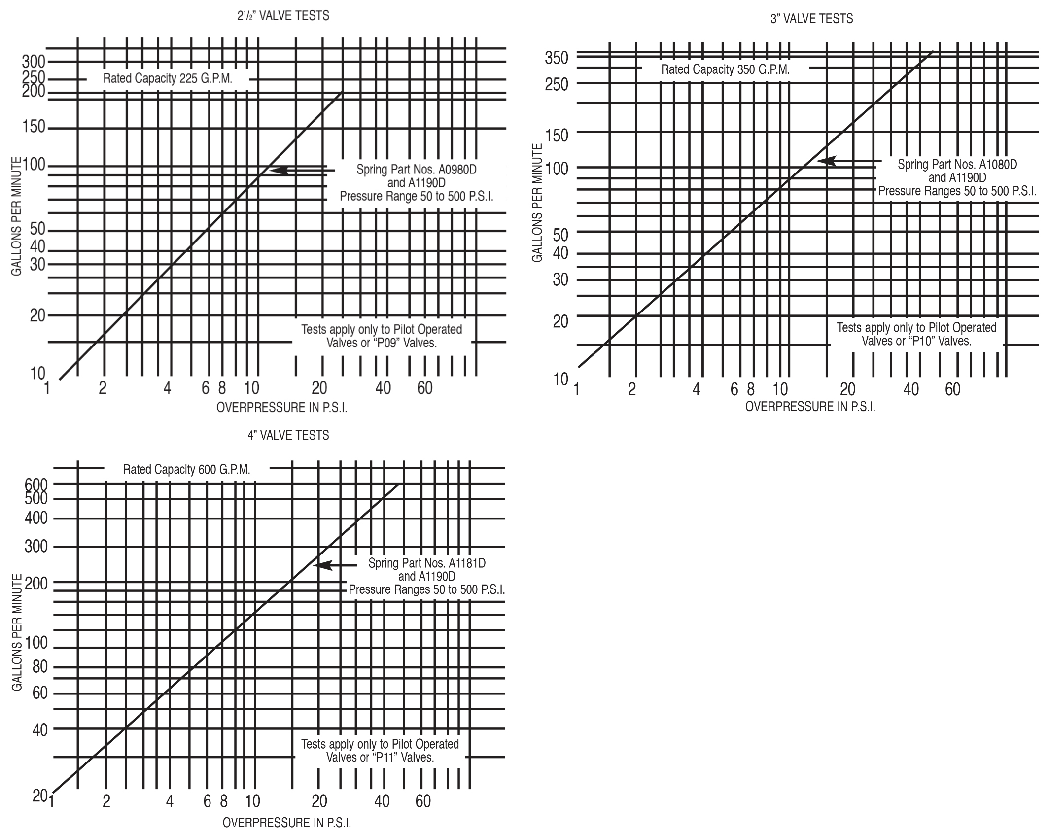
Overpressure: The pressure increase or accumulation above the set pressure when the valve is discharging flow.