V-Series Standard with Threaded Connections

Models

VB: Brass

VJ: Cast Iron

VS: Cast Steel

VSS: Stainless Steel

VJ‐SP: Cast Iron with Steel Parts


  • API 520 & 614 Approved
  • Chatter-free operation
  • Mount in any position
  • Suitable for continuous duty


Size Range: 3/8″ – 2″
Pressures: 3 – 1000 psi
Flow Rate: Up to 150 gpm

INSTALLATION, MAINTENANCE & OPERATION


Installation

Fulflo valves can be mounted in any position. A tee may be inserted in the pump discharge line to mount the valve. The correct size of the valve should be installed, preferably matching the pump discharge line. Screw the valve into the nipple in the tee, or in the case of the flange style, bolt the valve to the companion flange screwed into the nipple. When the valve is used for frequent bypassing of oil pressure, its outlet should be piped back to the tank. Care must be taken to have the discharge well below the oil level in the tank to prevent air entrainment and erratic operation.


Only if the valve is used as safety or overload relief and operates infrequently may its discharge be piped back into the pump suction line. Frequent or continuous operation under these conditions will cause excessive heating of the oil and possible damage.


Setting Valves

Valves may be set with a hydraulic hand pump for cracking pressure. If a test stand is available, the valve should be connected to the discharge header with the pump bypass open, and the bypass gradually closed until the desired pressure registers on the gauge. Adjust valve adjusting screw until valve slightly bleeds at the set bypass pressure and lock adjusting screw.


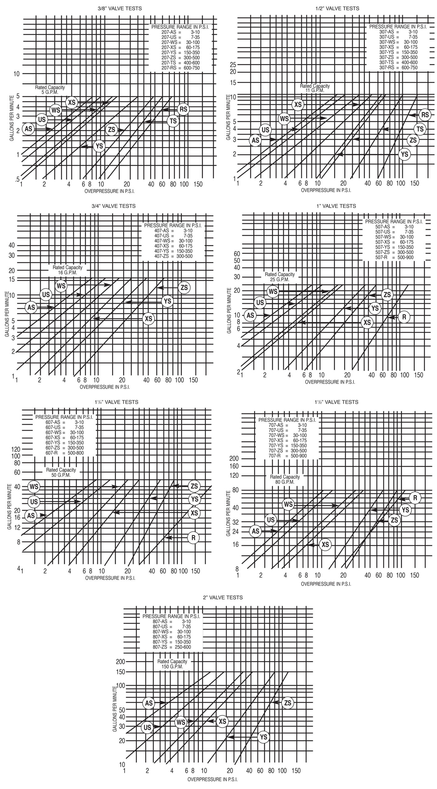
Fulflo valves are not designed to be positive shut-off and will pass a minimal amount of leakage before the set pressure. If a valve is required to bypass a given amount of fluid at a given pressure, a test stand having a flow meter in the pump discharge line must be available. With a valve adjusted for cracking pressure as above, continue closing the bypass until the required flow registers on the flow meter and observe pressure. Readjust pressure, if necessary, to obtain desired pressure at desired flow.


Maintenance & Operation

Fulflo valves provide reliable “chatter-free” operations when the system is free of abrasives and foreign matter. Continuous filtration of the liquid used is strongly recommended.

TYPICAL DISASSEMBLY OF STANDARD TYPE VALVE

To dismantle valve for inspection or cleaning:


  1. Remove cap “B”
  2. Remove O-Ring “E”
  3. Remove lock nut “F”
  4. Remove adjusting screw “C”
  5. Remove retainer “D”
  6. Remove spring “G”
  7. Remove piston “I”
  8. Remove stop ring “H” (Not Recommended-Special tooling is required to install new stop ring)

Inspect valve bore and piston for wear and scoring. Replace broken or damaged parts. Clean all parts thoroughly and re-assemble by reversing the above procedure.


ASSEMBLY NUMBER IDENTIFICATION CHART

Symbol Number Designation Code Description
1 Style None
H
Standard Model
Handwheel Model
2 Series V
3 Material J
B
S
SS
Cast iron
Brass
Steel
Stainless Steel (300 Series Stainless)
4 Connections None
F
Threaded Connections
Flange Connections 300# Flange Class Standard
(250# Flange Class – Cast Iron Standard)
5 Size -2
-3
-4
-5
-6
-7
-8
3/8”
1/2”
3/4”
1”
11/4
11/2
2”
6, 7, 8 ASA
Flange
Rating
None
-150
-600
300# Flange Standard (no designation required)
9 Flange Style
150# and 600#
Only
A
B
C
D
Raised Face, Staggered Bolt Centers
Smooth Face, Staggered Bolt Centers
Raised Face, Bolts on Valve Centerline
Smooth Face, Bolts on Valve Centerline
10 O-Ring
Material
R
RV
RS
RT
RA
EPR
RN
Buna (standard)
Viton
Silicone
Teflon
Aflas
Ethylene Propylene
Neoprene
11 Options SP
P
Steel Parts (used on cast iron only)
Panel Mount on Handwheel Series
12 Piston
Material
/HS
/SS
/3SS
Hardened Steel
416 Stainless Steel
303 Stainless Steel (for stainless valves only)
13 Spring

(+/-1-5 PSI ON ALL SPRING RANGES)
/AS
/US
/WS
/XS
/YS
/ZS
Pressure Range = 3 – 10 psi (spring color: black)
Pressure Range = 7 – 35 psi (spring color: red)
Pressure Range = 30 – 100 psi (spring color: green)
Pressure Range = 60 – 175 psi (spring color: yellow)
Pressure Range = 150 – 350 psi (spring color: white)
Pressure Range = 300 – 500 psi (spring color: blue)
14 Setting Desired Set Pressure

Examples

VJ-5RVSP/HS/WS

V

J

-5

RV

SP

/HS

/WS

Series
Cast Iron
1”
Viton O-Ring
Steel Parts
H.S. Piston
WS Spring

VJ-5R/HS/WS

V

J

-5

R

/HS

/WS

Series
Cast Iron
1”
Buna O-Ring
H.S. Piston
WS Spring

VJ-5-150AR/HS/WS

V

J

-5

-150

A

R

/HS

/WS

Series
Cast Iron
1”
Rating
Style
Buna O-Ring
H.S. Piston
WS Spring


DIMENSIONS & PARTS

Dimensions in Inches


Valve Size AA BB CC DD – ref
3/8″ 511/32 13/8 13/8 13/8
1/2″ 63/16 111/16 17/16 17/16
3/4″ 615/16 115/16 113/16 111/16
1″ 87/32 29/32 29/32 21/16
11/4 99/16 29/16 29/16 21/2
51/2 111/16 211/16 211/16 27/16
2″ 13 3 3 31/4

    Cutaway Drawing


Parts List


Valve Size

Sym. Name Model 3/8” 1/2” 3/4” 1” 11/4 11/2 2”
A Body VJ, VJ-SP
VB
VS
VSS
200
200-B
200-S
200-SS
300
300-B
300-S
300-SS
400
400-B
400-S
400-SS
500
500-B
500-S
500-SS
600
600-B
600-S
600-SS
700
700-B
700-S
700-SS
800
800-B
800-S
800-SS
B Cap (O-Ring Seal) VJ, VJ-SP
VB
VS
VSS
201-SR
201-BR
201-SR
201-SSR
301-SR
301-BR
301-SR
301-SSR
401-R
401-BR
401-SR
401-SSR
501-R
501-BR
501-SR
501-SSR
601-R
601-BR
601-SR
601-SSR
701-R
701-BR
701-SR
701-SSR
801-R
801-BR
801-SR
801-SSR
C Adjusting Screw VJ, VB
VS, VJ-SP
VSS
202-B
202-S
202-SS
302-B
302-S
302-SS
402-B
402-S
402-SS
502-B
502-S
502-SS
602-B
602-S
602-SS
702-B
702-S
702-SS
802-B
802-S
802-SS
D Retainer VJ, VB
VS, VJ-SP
VSS
203-B
203-S
203-SS
303-B
303-S
303-SS
403-B
403-S
403-SS
503-B
503-S
503-SS
603-B
603-S
603-SS
703-B
703-S
703-SS
803-B
803-S
803-SS
E O-Ring+ VJ, VJ-SP, VB, VS
VSS
204-*
204-RT
304-*
304-RT
404-*
404-RT
504-*
504-RT
604-*
604-RT
704-*
704-RT
804-*
804-RT
F Lock Nut VJ, VJ-SP, VS, VB
VSS
205-S
205-SS
305-S
305-SS
405-S
405-SS
505-S
505-SS
605-S
605-SS
705-S
705-SS
805-S
805-SS
G Spring+ All Models 207-** 307-** 407-** 507-** 607-** 707-** 807-**
H Stop Ring VJ, VB
VS, VJ-SP
VSS
208-B
208-S
208-SS
308-B
308-S
308-SS
408-B
408-S
408-SS
508-B
508-S
508-SS
608-B
608-S
608-SS
708-B
708-S
708-SS
808-B
808-S
808-SS
I Piston+ Hardened Steel
416 Stainless Steel
303 Stainless Steel
206
206-A
206-SS
306
306-A
306-SS
406
406-A
406-SS
506
506-A
506-SS
606
606-A
606-SS
706
706-A
706-SS
806
806-A
806-SS
B Cap (Gasket Seal) VJ, VJ-SP
VB
VS
201-S
201-B
201-S
301-S
301-B
301-S
401
401-B
401-S
501
501-B
501-S
601
601-B
601-S
701
701-B
701-S
801
801-B
801-S
E Gasket+ VJ, VB
VS, VJ-SP
204
204-S
304
304-S
404
404-S
504
504-S
604
604-S
704
704-S
804
804-S


PERFORMANCE DATA


All valve tests 110˚F to 120˚F Oil Viscosity 150 SSU at 100˚F

(Charts good from 30 to 500 SSU)


Overpressure: The pressure increase or accumulation above the set pressure when the valve is discharging flow.