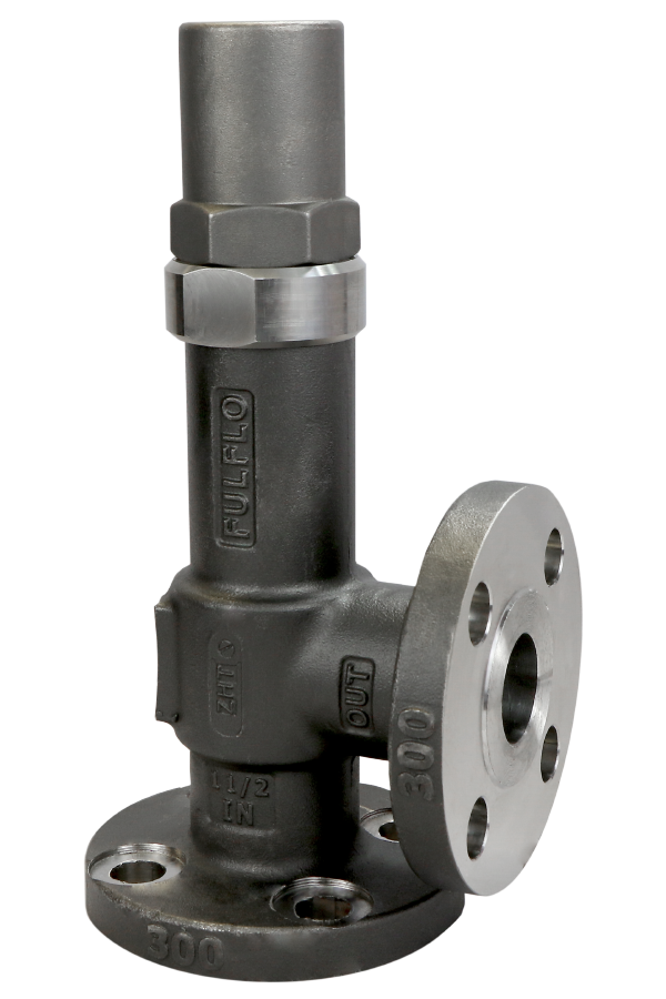
Models
FVBF: Brass
FVJF: Cast Iron
FVSF: Cast Steel
FVSSF Stainless Steel
- API 520 & 614 Approved
- Chatter-free operation
- Mount in any position
- Suitable for continuous duty
Size Range: 1″ – 2″
Pressures: 2 – 1000 psi
Flow Rate: Up to 150 gpm
FVBF: Brass
FVJF: Cast Iron
FVSF: Cast Steel
FVSSF Stainless Steel
Size Range: 1″ – 2″
Pressures: 2 – 1000 psi
Flow Rate: Up to 150 gpm
Fulflo valves can be mounted in any position. A tee may be inserted in the pump discharge line to mount the valve. The correct size of the valve should be installed, preferably matching the pump discharge line. Screw the valve into the nipple in the tee, or in the case of the flange style, bolt the valve to the companion flange screwed into the nipple. When the valve is used for frequent bypassing of oil pressure, its outlet should be piped back to the tank. Care must be taken to have the discharge well below the oil level in the tank to prevent air entrainment and erratic operation.
Only if the valve is used as safety or overload relief and operates infrequently may its discharge be piped back into the pump suction line. Frequent or continuous operation under these conditions will cause excessive heating of the oil and possible damage.
Valves may be set with a hydraulic hand pump for cracking pressure. If a test stand is available, the valve should be connected to the discharge header with the pump bypass open, and the bypass gradually closed until the desired pressure registers on the gauge. Adjust valve adjusting screw until valve slightly bleeds at the set bypass pressure and lock adjusting screw.
Fulflo valves are not designed to be positive shut-off and will pass a minimal amount of leakage before the set pressure. If a valve is required to bypass a given amount of fluid at a given pressure, a test stand having a flow meter in the pump discharge line must be available. With a valve adjusted for cracking pressure as above, continue closing the bypass until the required flow registers on the flow meter and observe pressure. Readjust pressure, if necessary, to obtain desired pressure at desired flow.
Fulflo valves provide reliable “chatter-free” operations when the system is free of abrasives and foreign matter. Continuous filtration of the liquid used is strongly recommended.

To dismantle valve for inspection or cleaning:
Inspect valve bore and piston for wear and scoring. Replace broken or damaged parts. Clean all parts thoroughly and re-assemble by reversing the above procedure.
The Fulflo FV-Series valve includes a new safer design that prevents liquid and gasses from venting out of the valve during normal operation and adjustment conditions. This valve has been specially designed to prevent the adjusting screw from backing out while making adjustments to the pressure setting. An O-ring has been incorporated around the adjusting screw to further prevent liquid from escaping.
The FV-Series valves can be mounted in any position with sizes ranging from 3/8” through 2”, and will operate efficiently with any application or viscosity at pressures from 2 to 1000 psi. Flange or screw connections are available in brass, cast iron, steel, or stainless steel. All parts are completely interchangeable and convertible with other Fulflo V-Series valves.
These valves offer Fulflo’s patented “chatter-free” performance and are ideally suited for hydraulic and lubricating system protection. All Fulflo valves include a patented modulating piston design with absolute or differential pressure operation. Our advanced modulating operation allows Fulflo valves to be used in many different applications including positive displacement or centrifugal pump and system protection. Fulflo valves can be mounted in any position.
| Symbol Number | Designation | Code | Description |
|---|---|---|---|
| 1 | Series | FV | |
| 2 | Material | J B S SS |
Cast iron Brass Steel Stainless Steel (300 Series Stainless) |
| 3 | Connections | None F |
Screw Connections Flange Connections 300# Flange Class Standard (250# Flange Class – Cast Iron Standard) |
| 4 | Size | -2 -3 -4 -5 -6 -7 -8 |
3/8” 1/2” 3/4” 1” 11/4” 11/2” 2” |
| 5, 6, 7 | ASA Flange Rating |
None -150 -600 |
300# Flange Standard (no designation required) |
| 8 | Flange Style 150# & 600# only |
A B C D |
Raised Face, Staggered Bolt Centers Smooth Face, Staggered Bolt Centers Raised Face, Bolts on Valve Centerline Smooth Face, Bolts on Valve Centerline |
| 9 | O-Ring Material Note: No Teflon O-Rings
|
R RV RS RA EPR RN |
Buna (Standard) Viton Silicone Aflas Ethylene Propylene Neoprene |
| 10 | Piston Material |
/HS /SS /3SS |
Hardened Steel 416 Stainless Steel 303 Stainless Steel (For Stainless Valves Only) |
| 11 | Spring
(+/-1-5 PSI ON ALL SPRING RANGES) |
/AS /US /WS /XS /YS /ZS |
Pressure Range = 3 – 10 psi (spring color: black) Pressure Range = 7 – 35 psi (spring color: red) Pressure Range = 30 – 100 psi (spring color: green) Pressure Range = 60 – 175 psi (spring color: yellow) Pressure Range = 150 – 350 psi (spring color: white) Pressure Range = 300 – 500 psi (spring color: blue) |
| 12 | Setting | Desired Set Pressure |
FVJF-5RV/HS/WS |
|||||||
FV |
J |
F |
-5 |
RV |
/HS |
/WS |
|
FVJF-5R/HS/WS |
||||||
FV |
J |
F |
-5 |
R |
/HS |
/WS |
FVJF-5-150AR/HS/WS |
||||||||||
FV |
J |
F |
-5 |
-150 |
A |
R |
/HS |
/WS |
||
| Valve Size | AA | BB |
| 1″ | 105/16 | 31/2 |
| 11/4“ | 1113/16 | 33/4 |
| 11/2“ | 125/8 | 41/16 |
| 2″ | 155/16 | 49/16 |
Note: Dimensions reflect 150# and 300# only
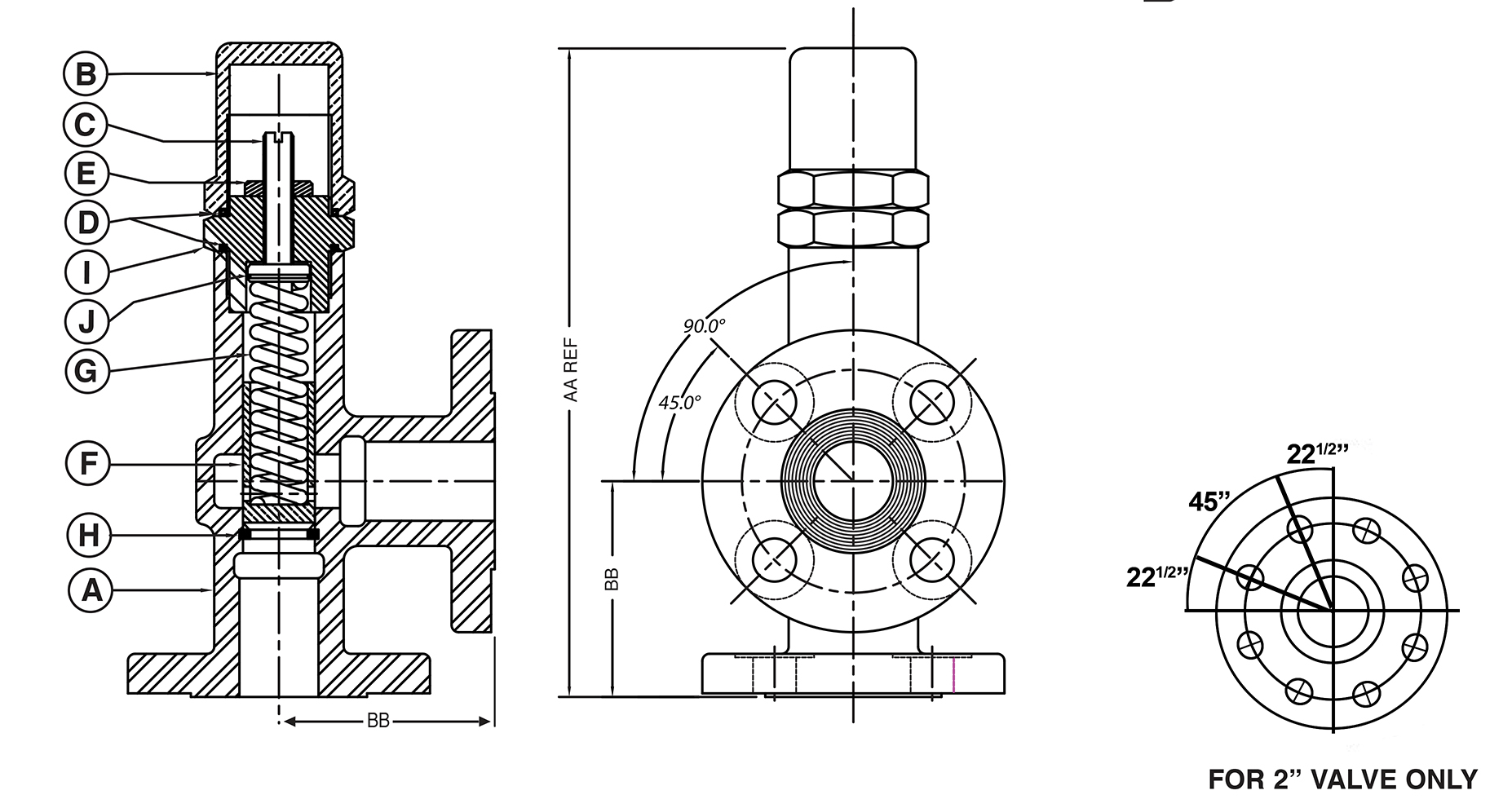
Valve Size |
|||||||||||||||||
| Sym. | Name | Model | 1” | 11/4” | 11/2” | 2” | |||||||||||
| A | Body | FVJF FVBF FVSF FVSSF |
500-F 500-BF 500-SF 500-SSF |
600-F 600-BF 600-SF 600-SSF |
700-F 700-BF 700-SF 700-SSF |
800-F 800-BF 800-SF 800-SSF |
|||||||||||
| B | Cap | FVJF FVBF FVSF FVSSF |
501-R 501-BR 501-SR 501-SSR |
601-R 601-BR 601-SR 601-SSR |
701-R 701-BR 701-SR 701-SSR |
801-R 801-BR 801-SR 801-SSR |
|||||||||||
| C | Adjusting Screw | FVJF FVBF FVSF FVSSF |
502-S8 502-B8 502-S8 502-SS8 |
602-S8 602-B8 602-S8 602-SS8 |
702-S8 702-B8 702-S8 702-SS8 |
802-S8 802-B8 802-S8 802-SS8 |
|||||||||||
| D | O-Ring+ (2 Req.) |
FVJF FVBF FVSF FVSSF |
504-* 504-* 504-* 504-* |
604-* 604-* 604-* 604-* |
704-* 704-* 704-* 704-* |
804-* 804-* 804-* 804-* |
|||||||||||
| E | Lock Nut | FVJF FVBF FVSF FVSSF |
505-S 505-S 505-S 505-SS |
505-S 505-S 505-S 505-SS |
505-S 505-S 505-S 505-SS |
505-S 505-S 505-S 505-SS |
|||||||||||
| F | Piston+ | Hardened Steel 416 Stainless Steel 303 Stainless Steel |
506 506-A 506-SS |
606 606-A 606-SS |
706 706-A 706-SS |
806 806-A 806-SS |
|||||||||||
| G | Spring+ | All Models | 507-** | 607-** | 707-** | 807-** | |||||||||||
| H | Stop Ring | FVJF FVBF FVSF FVSSF |
508-S 508-B 508-S 508-SS |
608-S 608-B 608-S 608-SS |
708-S 708-B 708-S 708-SS |
808-S 808-B 808-S 808-SS |
|||||||||||
| I | Bonnet | FVJF FVBF FVSF FVSSF |
523-S4 523-B4 523-S4 523-SS4 |
623-S4 623-B4 623-S4 623-SS4 |
723-S4 723-B4 723-S4 723-SS4 |
823-S4 823-B4 823-S4 823-SS4 |
|||||||||||
| J | O-Ring+ (1 Req.) |
FVJF FVBF FVSF FVSSF |
7003-* 7003-* 7003-* 7003-* |
7061-* 7061-* 7061-* 7061-* |
7062-* 7062-* 7062-* 7062-* |
504-* 504-* 504-* 504-* |
|||||||||||
All valve tests 110˚F to 120˚F Oil Viscosity 150 SSU at 100˚F
(Charts good from 30 to 500 SSU)
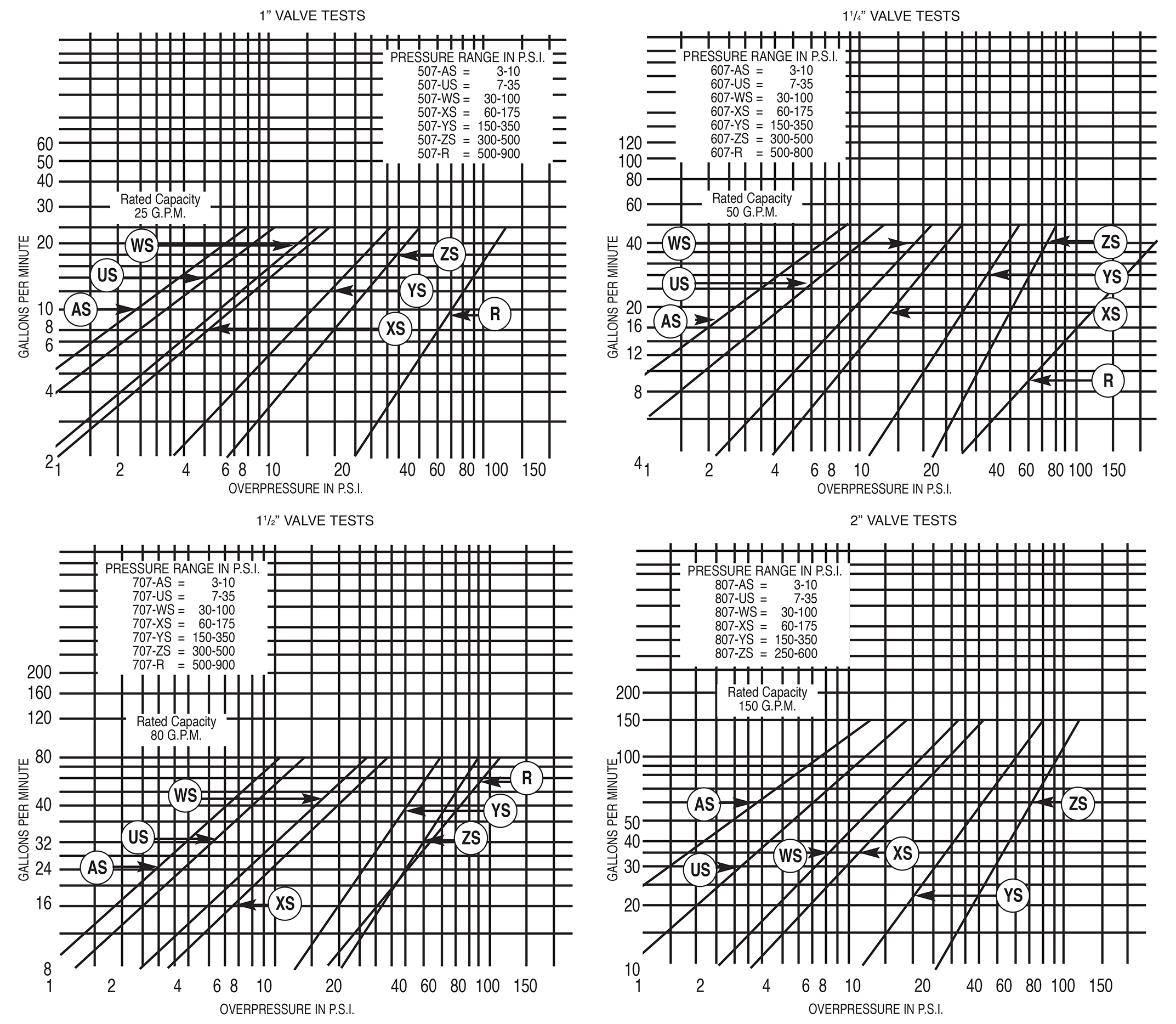
Overpressure: The pressure increase or accumulation above the set pressure when the valve is discharging flow.