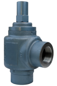
Models
AAD: Cast Iron
ACD: Cast Steel
ASSD: Stainless Steel
- API 520 & 614 Approved
- Chatter-free operation
- Mount in any position
- Suitable for continuous duty
Size Range: 2.5″ and 3″
Pressures: 7 – 150 psi
Flow Rate: 150 – 350 gpm
AAD: Cast Iron
ACD: Cast Steel
ASSD: Stainless Steel
Size Range: 2.5″ and 3″
Pressures: 7 – 150 psi
Flow Rate: 150 – 350 gpm
Fulflo valves can be mounted in any position. A tee may be inserted in the pump discharge line to mount the valve. The pipelines carrying the heavy valves must be well supported and overhung weights avoided. The correct size of the valve must be used, preferably equal to the size of the pipeline to which they are connected. Threaded valves (AAD and ACD) may be threaded into pipe nipples. Overhung weights on threads should be avoided. The outlet of the valve should be piped to the supply tank unless specific applications call for alternate piping of return lines. Care must be taken to have the discharge well below the oil level in the tank to prevent air entrainment and erratic operation.
The valve may be set with a hydraulic hand pump for cracking pressure. If a test stand is available, the valve should be connected to the discharge header with the pump bypass open, and the bypass gradually closed until the desired pressure registers on the gauge. For Direct Acting valves, adjust valve adjusting screw until valve slightly bleeds at the set bypass pressure and lock adjusting screw. If a valve is required to bypass a given amount of fluid at a given pressure, a test stand having a flow meter in the pump discharge line must be available. With a valve adjusting for cracking pressure as above, continue closing the bypass until the required flow registers on the flow meter and observe pressure. Readjust pressure, if necessary to obtain desired pressure at desired flow.
Fulflo valves provide reliable “chatter-free” operations when the system is free of abrasives and foreign matter. Continuous filtration of the liquid used is strongly recommended.
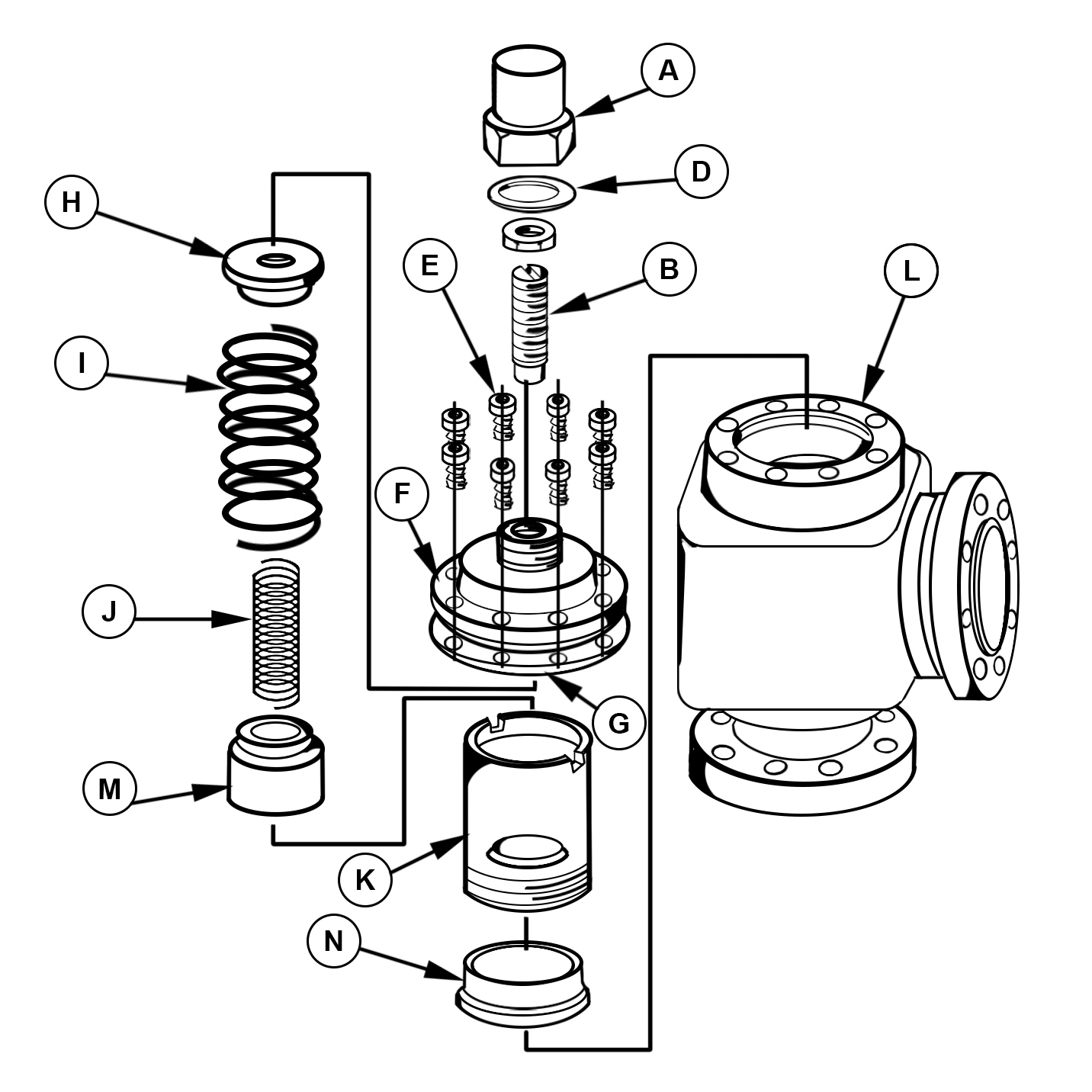
To dismantle the valve for inspection or cleaning:
Inspect cylinder bore and piston for wear or scoring. Replace broken or damaged parts. Clean all parts thoroughly and re-assemble as follows:
| Symbol Number | Designation | Code | Description |
|---|---|---|---|
| 1 | Series | A | |
| 2 | Material | A C SS |
Cast Iron Cast Steel Stainless Steel |
| 3 | Type | D P |
Direct Acting Internal Pilot Operated |
| 4 & 5 | Size | 09 10 11 |
21/2” 3” 4” |
| 6 | Connection | None F |
Screw Type (21/2″ and 3” only) Flange |
| 7, 8, 9 | ASA Flange Rating |
150# 300# 600# |
|
| 10 | Flange Style Only |
A B C D |
Raised Face, Staggered Bolt Centers Smooth Face, Staggered Bolt Centers Raised Face, Bolts on Valve Centerline Smooth Face, Bolts on Valve Centerline |
| 11 | O-Ring Material |
R RV RS RT RA EPR RN |
Buna O-Ring Cap Seal (Standard) Viton O-Ring Cap Seal Silicone O-Ring Cap Seal Teflon O-Ring Cap Seal Aflas O-Ring Cap Seal Ethylene Propylene Neoprene |
| 12 | Piston Material |
/HS /SS /3SS |
Hardened Steel 416 Stainless Steel 303 Stainless Steel (For Stainless valves only) |
| 13 | Spring
(+/-1-5 PSI ON ALL
|
A0960 D A0961C A0960D & A0970D A0961C & A0971C A1060D A1061C A1060D & A1070D A1061C & A1071C A1160D A1160D & A1170D |
Pressure Range = 7 –57 psi Pressure Range = 8 – 75 psi Pressure Range = 14 – 115 psi Pressure Range = 16 –150 psi Pressure Range = 5 – 50 psi Pressure Range = 5 – 67 psi Pressure Range = 10 –100 psi Pressure Range = 10 –135 psi Pressure Range = 2 – 37 psi Pressure Range = 4 – 75 psi |
| 14 | Setting | Desired Set Pressure |
ACD09R |
|||||||
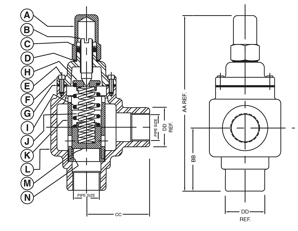
Specify:
| Valve Size | AA | BB | CC | DD |
| 21/2″ | 159/16 | 51/2 | 51/16 | 4 |
| 3″ | 171/2 | 65/8 | 63/8 | 4 |
Valve Size |
||||||||||||||
| Symbol | Name | Model | 21/2” | 3” | ||||||||||
| A | Cap | AAD, ACD ASSD |
A1101CR A1101SSR |
A1013CR A1013SSR |
||||||||||
| B | Adjusting Screw | AAD, ACD ASSD |
A0922C A0922SS |
A1022C A1022SS |
||||||||||
| C | Lock Nut | AAD, ACD ASSD |
605-S 605-SS |
705-S 705-SS |
||||||||||
| D | O-Ring+ | AAD, ACD ASSD |
604-* 604-* |
704-* 704-* |
||||||||||
| E | Cap Screw | All Models | 3/8×1 SHCS | 3/8×1 SHCS | ||||||||||
| F | Bonnet | AAD ACD ASSD |
A0909A A0909C A0909SS |
A1009A A1009C A1009SS |
||||||||||
| G | Gasket+ | AAD, ACD ASSD |
A0903E A0903RT |
A1003E A1003RT |
||||||||||
| H | Spring Retainer | AAD, ACD ASSD |
A0916C A0916SS |
A1016C A1016SS |
||||||||||
| I | Spring+ | All Models | See Chart* | See Chart* | ||||||||||
| J | Spring+ | All Models | See Chart* | See Chart* | ||||||||||
| K | Cylinder+ | AAD, ACD ASSD |
A0908C A0908SS |
A1008C A1008SS |
||||||||||
| L | Body | AAD ACD ASSD |
A0900A A0900C A0900SS |
A1000A A1000C A1000SS |
||||||||||
| M | Piston+ Hardened Steel 416 Stainless Steel 303 Stainless Steel |
– AAD, ACD AAD, ACD ASSD (only) |
– A0906C A0906D A0906SS |
– A1006C A1006D A1006SS |
||||||||||
| N | Retainer Bushing | AAD, ACD ASSD |
A0911C A0911SS |
A1011C A1011SS |
||||||||||
+ Recommended spare parts
* See Assembly Number Identification Chart; Symbol Number 13
All valve tests 110˚F. to 120˚F. Oil Viscosity 150 SSU at 100˚F
(Charts good from 30 to 500 SSU)
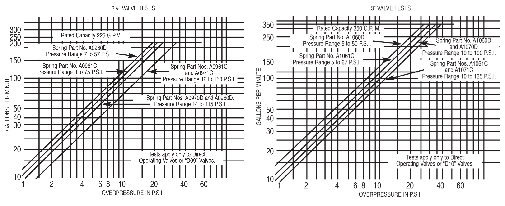
Overpressure: The pressure increase or accumulation above the set pressure when the valve is discharging flow.